Saturday, October 24, 2015

Configuring Basic Cisco IPS Signature Properties

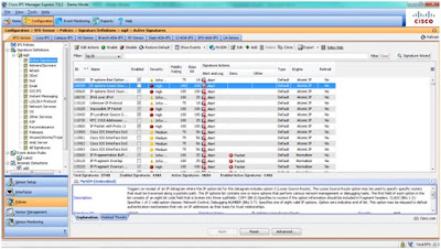
The signatures in the Cisco IPS Sensor can be accessed through the Cisco IDM by choosing Configuration > Policies  > Signature Definitions > sig0 and then clicking All Signatures to access the Signature Configuration panel. The All Signatures view is only visible when the Sig0 is expanded. By default, the signature configuration panel displays signatures that are lissted by signature ID number. The All Signature database view displays all signatures available in the sensor signature set; when each signature set is clicked on, it displays the list of signatures grouped under it in the view pane.

The signature sets are as follows:

* Active Signatures: Displays all non-retired signatures

* Adware/Spyware: Displays signatures that are designed to address adware and spyware issues

* Attack: Displays attack-based signatures that are grouped by attack types

* Configurations: Displays configuration-based signatures that mitigate atacks typically because of misconfiguration

* DDoS: Displays distributed denial of service (DDoS) signatures

* DoS: Displays denial of service signatures

* Email: Displays email signatures by protocol, such as Internet Message Access Protocol (IMAP) or Simple Mail Transfer Protocol (SMTP)

* IOS IPS: Displays signatures in the IOS IPS

* Instant Messaging: Displays instant messaging (IM) signatures grouped by IM application

* L2/L3/L4 Protocol: Displays signatures grouped by network protocol type, including Address Resolution Protocol (ARP), IP fragment, IP version 6 (IPv6), and others

* Network Services: Displays signatures that are based on network service protocols, such as DHCP

* OS: Displays signatures grouped by operating system type

* Other Services: Displays signatures based on application layer services, such as FTP, HTTP, and others

* P2P: Displays signatures based on different peer-to-peer file-sharing applications

* Reconnaissance: Display signatures based on discovery protocols, such as Internet Control Message Protocol (ICMP) sweeps

* Releases: Enables you to view signatures grouped by signature update releases

* Telepresence: Enables you to display Telepresence-based signatures

* UC Protection: Displays Cisco Unified Communications-based signatures

* Viruses/Worms/Trojans: Displays signatures based on malware that is defined as these three types

* Web Server: Enables you to display signatures based on web servers

* All Signatures: Displays all defined signatures


Enabling and Disabling Signatures

Enabling a signature makes the signature inspect traffic; when it is disabled, it does not inspect traffic. The following steps walk you through enabling a signature:

Step 1: Click Configuration and choose Policies > Signature Definitions > Sig0 > Active Signatures. The Signature Configuration panel is displayed.

Step 2: Locate the signature that you want to enable.

Step 3: A signature that is already enabled has a check mark in the check box. If the signature is disabled, the check box is empty.

Step 4: If the signature is currently disabled, select the signature by clicking it.

Step 5: Click Apply to apply your changes and save the updated configuration. To disable a signature that is already disabled, deselect the check box in the Enabled column.

Tip: To enable multiple signatures at the same time, hold down the Ctrl or Shift key and click the signatures that you would like to enable; then righ-click one of the selected signatures and click Enable.

Retiring and Activating Signatures

Signatures that are not being used are no longer applicable to the network resources being protected should be retired to improve sensor performance. Retiring a signature removes it from the set of currently available signatures, which are part of the signature database. After the signature is retired, it is removed from memory but stored in flash. For a signature to function, the signature must be both activated and enabled.

You can activate signatures you have previously retired. When this is done, the sensor rebuilds its configurations and the signature is once again added to the set of currently active signatures. Follow these steps to retire or activate a signature:

Step 1: Click Configuration and choose Policies > Signature Definitions > Sig0 > All Signatures. The Signature Configuration panel is displayed.

Step 2: Select a signature that you want to retire or activate, and click Edit on the toolbar. The Edit Signature window opens.

Step 3: Scroll down to the Status section and click the Retired field.

Step 4: Select yes or No from the drop-down list.

Alternatively, you can retire or activate signature from the Signature Configuration panel by following these steps:

Step 1: Select a signature that you want to retire or activate.

Step 2: Right-click the signature

Step 3: Choose the Change Status to and then choose Active or Retired.

Note: Retiring or activating signatures can take 30 minutes or longer.


Saturday, October 17, 2015

Cisco IPS Manager Express (IME) 7.0

The Cisco IPS Manager express (IME) is a web-based Java Web Start application that enables you to configure, manage, and monitor the Cisco IPS sensor. Both Microsoft Internet Explorer and Mozilla Firefox web browsers are supported.

The Home pane contains various knobs and widgets. These knobs and widgets can quickly help the administrator/user determine the health of the sensor and gets an overview of current network activity. The following gadgets are presented on the Home pane by default:

* Licensing

* Sensor Information

* Interface Status

* Sensor Health

* CPU, Memory, and Load

The Home pane can be customized by adding, removing, and renaming gadgets and dashboards. The available sensor gadgets can be displayed by clicking the Add Gadgets button.


You can modify the Cisco IPS sensor settings simply by opening the Cisco IDM Configuration pane by clicking the Configuration button on the Cisco IDM toolbar. For the most part, the majority of the Cisco IPS sensor features can be configured from here. There are four main configuration items in the Configuration pane of the Cisco IDM:

* Sensor Management: Configure various sensor device management functions.

* Sensor Setup: Reconfigure basic sensor settings.

* Interfaces: Configure individual sensing interfaces, as well as configure them in a particular operational
mode.

* Policies: Configure and tune Cisco IPS security policies to achieve optimal traffic analysis and response functionality.


The Cisco IDM supports the monitoring of the Cisco IPS sensor events. Click the Monitoring button to display the Cisco IPS sensor events, health, and performance indicators, and traffic and operational statistics.


Sunday, October 11, 2015

Cisco IPS 4240 version 7 in GNS3

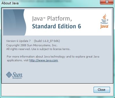
I've been searching and trying to emulate IDS/IPS using the new GNS3 version 1.3.9 (need to register) for quite some time. There's a lot of tutorials and qemu files scattered all over the Internet for Cisco 4235 (IDS only) using version 6 but not for Cisco IPS 4240 version 7. The qemu files and links for Cisco IPS version 7 are already unavailable and the only way I was able to emualte it was using an ova file running in VMware Workstation 10. I've used Java 6 update 7 and disabled TLS 1.1 and 1.2 in IE11 for IDM (HTTPS) to work.


sensor# configure terminal
sensor(config)# service ?
aaa                            Enter configuration mode for AAA options.
analysis-engine                Enter configuration mode for global analysis engine
                               options.
anomaly-detection              Enter configuration mode for anomaly-detection.
authentication                 Enter configuration mode for user authentication options.
event-action-rules             Enter configuration mode for the event action rules.
external-product-interface     Enter configuration mode for the interfaces to external
                               products.
global-correlation             Enter configuration mode for global correlation
                               configuration.
health-monitor                 Enter configuration mode for health and security
                               monitoring.
host                           Enter configuration mode for host configuration.
interface                      Enter configuration mode for interface configuration.
logger                         Enter configuration mode for debug logger.
network-access                 Enter configuration mode for the network access controller.
notification                   Enter configuration mode for the notification application.
signature-definition           Enter configuration mode for the signature definition.
ssh-known-hosts                Enter configuration mode for configuring SSH known hosts.
trusted-certificates           Enter configuration mode for configuring trusted
                               certificates.
web-server                     Enter configuration mode for the web server application.
sensor(config)# service host
sensor(config-hos)# ?
auto-upgrade           Configure Auto Upgrade Settings.
crypto                 Configure cryptographic settings.
default                Set the value back to the system default setting.
exit                   Exit service configuration mode.
network-settings       Configure network settings.
ntp-option             Select whether to synchronize the sensor's clock to an NTP time
                       server.
password-recovery      Option to allow password recovery.
show                   Display system settings and/or history information.
summertime-option      Select whether summertime (Daylight Savings Time) begins and ends
                       at the same time every year (recurring), or just this year
                       (non-recurring), or summertime is disabled.
time-zone-settings     Configure time zone settings.
sensor(config-hos)# network-settings
sensor(config-hos-net)# ?
access-list              List of trusted hosts and/or networks.
default                  Set the value back to the system default setting.
dns-primary-server       Optional primary DNS server. Currently DNS is only used by the
                         collaboration service.
dns-secondary-server     Optional secondary DNS server. Currently DNS is only used by the
                         collaboration service.
dns-tertiary-server      Optional tertiary DNS server. Currently DNS is only used by the
                         collaboration service.
exit                     Exit network-settings configuration submode
ftp-timeout              The FTP client timeout (in seconds) used when communicating with
                         an FTP server.
host-ip                  The IP address/netmask, and default gateway used on the command
                         and control interface.
host-name                Network host name assigned to the sensor.
http-proxy               Optional HTTP/HTTPS proxy server.  Currently the proxy is only
                         used by the collaboration service.
login-banner-text        Banner to be displayed at login.
no                       Remove an entry or selection setting.
show                     Display system settings and/or history information.
telnet-option            Option to enable or disable the telnet server on the sensor.
sensor(config-hos-net)# host-ip ?
<A.B.C.D/nn,E.F.G.H>     The IP address/netmask, and default gateway used on the command
                         and control interface.
sensor(config-hos-net)# host-ip 10.1.1.1/24,10.1.1.2
sensor(config-hos-net)# access-list ?
<A.B.C.D>/nn     Network address of a trusted host or network.  To represent a single host
                 address, use /32 for the network mask.
sensor(config-hos-net)# access-list 10.1.1.0/24
sensor(config-hos-net)# telnet-option ?
enabled      Enable the telnet server on the sensor.
disabled     Disable the telnet server on the sensor.
sensor(config-hos-net)# telnet-option enabled
sensor(config-hos-net)# exit
sensor(config-hos)# exit
sensor(config)# username ?
<username>     Username to add to the system.
sensor(config)# username admin ?
<cr>
password      Enter user password.
privilege     User privilege level for local sensor.
sensor(config)# username admin privilege ?
administrator     Allows full system privileges.
operator          May modify most configuration.
service           Logs directly into a system shell.
viewer            No modification allowed view only.
sensor(config)# username admin privilege administrator ?
<cr>
password     Enter user password.
sensor(config)# username admin privilege administrator password cisco4240!   


Saturday, October 3, 2015

Initializing and Troubleshooting Cisco 4200 IPS Sensor

The Cisco 4200 series IPS version 7.0 is still valid and included (as of this writing) in the CCNP Security SITCS exam blueprint. Studying for this exam gave me a good insight on how IPS sensor works and its best practices.
To initialize the Cisco IPS sensor, you must first gain management access to one of the following methods:

* Console port: Requires the use of the RS-232 cable provided with the sensor and a terminal emulation program such as HyperTerminal, Putty, and so on. As discussed in the previous section, for console access when an IPS module is involved, the session command is the equivalent to console access.

* Secure Shell (SSH): Requires an IP address that has been assigned to the command and control interface through the CLI setup command and uses a supported SSH client. The SSH server in the sensor is enabled by default.

* Telnet: Requires an IP address that has been assigned to the command and control interface through the CLI setup command. You must enable this IP address to allow Telnet access. Telnet is disabled by default.

* HTTPS: Requires an IP address that has been assigned to the command and control interface through the CLI setup command and uses a supported web browser. HTTPS is enabled by default but can be disabled.

Note: Sensor intialization can only be done through the console connection, and after network settings are configured, SSH and Telnet are available.

After you have access, initialization can begin. The setup command begins the sensor initialization process and initiates an interactive dialogue. The interactive dialogue includes the following initialization tasks:

* Assign the sensor a host name.

* Assign an IP address and a subnet mask to the command and control interface.

Note: If the IP address of the sensor is changed later, you can regenerate the certificate (self-signed X.509) of the sensor.

* Assign a default route.

* Add and remove access control list (ACL) entries that specify which hosts are allowed to connect to the sensor.

* Configure a Domain Name System (DNS) and HTTP proxy server for use with global event correlation.

* Configure the date and time.

* Configure the level of participation of this sensor in the Cisco SensorBase.

* Enable or disable the Telnet server.

* Specify the web server port.

* Configure the sensor interfaces and virtual sensors.

* Configure threat prevention.


sensor# setup


    --- System Configuration Dialog ---

At any point you may enter a question mark '?' for help.
User ctrl-c to abort configuration dialog at any prompt.
Default settings are in square brackets '[]'.

Current Configuration:

service host
network-settings
host-ip 10.1.1.1/24,10.1.1.2
host-name sensor
telnet-option enabled
access-list 10.1.1.0/24
ftp-timeout 300
no login-banner-text
exit
time-zone-settings
offset 0
standard-time-zone-name UTC
exit
summertime-option disabled
ntp-option disabled
exit
service web-server
port 443
exit
service event-action-rules rules0
overrides
override-item-status Enabled
risk-rating-range 90-100
exit
exit

Current time: Thu Sep  3 13:44:48 2015

Setup Configuration last modified: Thu Sep 03 13:35:20 2015

Continue with configuration dialog?[yes]: yes
Enter host name[sensor]: IPS
Enter IP interface[10.1.1.1/24,10.1.1.2]:
Enter telnet-server status[enabled]:
Enter web-server port[443]: 8080
Modify current access list?[no]: no
Modify system clock settings?[no]: yes
  Use NTP?[no]: no
  Modify summer time settings?[no]: no
  Modify system timezone?[no]: yes
    Timezone[UTC]: SGT
    UTC Offset[0]: 8
Modify interface/virtual sensor configuration?[no]: no
Modify default threat prevention settings?[no]: no

The following configuration was entered.

service host
network-settings
host-ip 10.1.1.1/24,10.1.1.2
host-name IPS
telnet-option enabled
access-list 10.1.1.0/24
ftp-timeout 300
no login-banner-text
exit
time-zone-settings
offset 8
standard-time-zone-name SGT
exit
summertime-option disabled
ntp-option disabled
exit
service web-server
port 8080
exit
service event-action-rules rules0
overrides
override-item-status Enabled
risk-rating-range 90-100
exit
exit
[0] Go to the command prompt without saving this config.
[1] Return back to the setup without saving this config.
[2] Save this configuration and exit setup.

Enter your selection[2]:

Troubleshooting the initial configuration of the Cisco IPS sensor often starts with a common issue: the inaccessibility of the management interface of the sensor. Network issues or misconfigured sensor network settings often prevent accessing the sensor CLI through Telnet (if enabled), SSH, or HTTPS. To troubleshoot these issues, you must be connected to the sensor itself through its serial console (or using the session command if an IPS module).

Ping or traceroute are common tools when troubleshooting from a workstation to verify network connectivity. These same tools can be used from the sensor in addition to the show interfaces command or the setup command to verify network settings. Follow these steps to troubleshoot sensor management:

Step 1: Log in to the sensor CLI through a console or using the session command.

Step 2: Use the show interfaces command to verify that the sensor management interface is enabled.

sensor# show interfaces
Interface Statistics
   Total Packets Received = 0
   Total Bytes Received = 0
   Missed Packet Percentage = 0
   Current Bypass Mode = Auto_on
MAC statistics from interface Management0/0
   Interface function = Command-control interface
   Description =
   Media Type = TX
   Default Vlan = 0
   Link Status = Up
   Link Speed = Auto_1000
   Link Duplex = Auto_Full
   Total Packets Received = 375
   Total Bytes Received = 0
   Total Multicast Packets Received = 0
   Total Receive Errors = 0
   Total Receive FIFO Overruns = 0
   Total Packets Transmitted = 75
   Total Bytes Transmitted = 0
   Total Transmit Errors = 0
   Total Transmit FIFO Overruns = 0
MAC statistics from interface GigabitEthernet0/0
   Interface function = Sensing interface
   Description =
   Media Type = TX
   Default Vlan = 0
   Inline Mode = Unpaired
   Pair Status = N/A
   Hardware Bypass Capable = No
   Hardware Bypass Paired = N/A
   Link Status = Up
   Link Speed = Auto_
   Link Duplex = Auto_
   Missed Packet Percentage = 0
   Total Packets Received = 0
   Total Bytes Received = 0
   Total Multicast Packets Received = 0
   Total Broadcast Packets Received = 0
   Total Jumbo Packets Received = 0
   Total Undersize Packets Received = 0
   Total Receive Errors = 0
   Total Receive FIFO Overruns = 0
   Total Packets Transmitted = 0
   Total Bytes Transmitted = 0
   Total Multicast Packets Transmitted = 0
   Total Broadcast Packets Transmitted = 0
   Total Jumbo Packets Transmitted = 0
   Total Undersize Packets Transmitted = 0
   Total Transmit Errors = 0
   Total Transmit FIFO Overruns = 0
MAC statistics from interface GigabitEthernet0/1
   Interface function = Sensing interface
   Description =
   Media Type = TX
   Default Vlan = 0
   Inline Mode = Unpaired
   Pair Status = N/A
   Hardware Bypass Capable = No
   Hardware Bypass Paired = N/A
   Link Status = Up
   Link Speed = Auto_
   Link Duplex = Auto_
   Missed Packet Percentage = 0
   Total Packets Received = 0
   Total Bytes Received = 0
   Total Multicast Packets Received = 0
   Total Broadcast Packets Received = 0
   Total Jumbo Packets Received = 0
   Total Undersize Packets Received = 0
   Total Receive Errors = 0
   Total Receive FIFO Overruns = 0
   Total Packets Transmitted = 0
   Total Bytes Transmitted = 0
   Total Multicast Packets Transmitted = 0
   Total Broadcast Packets Transmitted = 0
   Total Jumbo Packets Transmitted = 0
   Total Undersize Packets Transmitted = 0
   Total Transmit Errors = 0
   Total Transmit FIFO Overruns = 0

Step 3: Use the setup command to make sure that the sensor IP address is unique.

sensor# setup

    --- System Configuration Dialog ---

At any point you may enter a question mark '?' for help.
User ctrl-c to abort configuration dialog at any prompt.
Default settings are in square brackets '[]'.

Current Configuration:

service host
network-settings
host-ip 10.1.1.1/24,10.1.1.2
host-name sensor
telnet-option enabled
access-list 10.1.1.0/24
ftp-timeout 300
no login-banner-text
exit
time-zone-settings
offset 0
standard-time-zone-name UTC
exit
summertime-option disabled
ntp-option disabled
exit
service web-server
port 443
exit
service event-action-rules rules0
overrides
override-item-status Enabled
risk-rating-range 90-100
exit
exit

Current time: Fri Sep  4 15:45:35 2015

Setup Configuration last modified: Fri Sep 04 15:39:32 2015

Continue with configuration dialog?[yes]:


Step 4: Use the show interfaces command to make sure that the management port is connected to an active network connection.

Step 5: Use the setup command to make sure that the IP address of the workstation that is trying to connect to the sensor is permitted in the ACL of the sensor.

Step 6: Make sure that the network configuration allows the workstation to connect to the sensor.

The ping and traceroute commands are tools that can be used to diagnose basic network connectivity. The sensor always sends ping and traceroute requests over its management interface. The sensor uses a User Datagram Protocol (UDP)-based traceroute algorithm.

sensor# ping 10.1.1.2
PING 10.1.1.2 (10.1.1.2): 56 data bytes
64 bytes from 10.1.1.2: icmp_seq=0 ttl=128 time=74.3 ms
64 bytes from 10.1.1.2: icmp_seq=1 ttl=128 time=1.0 ms
64 bytes from 10.1.1.2: icmp_seq=2 ttl=128 time=1.0 ms
64 bytes from 10.1.1.2: icmp_seq=3 ttl=128 time=1.0 ms

--- 10.1.1.2 ping statistics ---
4 packets transmitted, 4 packets received, 0% packet loss
round-trip min/avg/max = 1.0/19.3/74.3 ms

sensor# trace ?
<A.B.C.D>     Address of system to trace route to.
sensor# trace 10.1.1.2
traceroute to 10.1.1.2 (10.1.1.2), 4 hops max, 40 byte packets
 1  * * *
 2  * * *
 3  * * *
 4  * * *

A common reason for the management interface not comming up automatically is if a duplicate IP address on the network is detected. Use the setup or more current-config commands to make sure that the IP address of the sensor is unique and correct if necessary.

sensor# more ?
backup-config      Display the saved backup system configuration.
current-config     Display the current system configuration.
sensor# more current-config
! ------------------------------
! Current configuration last modified Fri Sep 04 15:39:32 2015
! ------------------------------
! Version 6.0(6)
! Host:
!     Realm Keys          key1.0
! Signature Definition:
!     Signature Update    S399.0   2009-05-06
!     Virus Update        V1.4     2007-03-02
! ------------------------------
service interface
exit
! ------------------------------
service authentication
exit
! ------------------------------
service event-action-rules rules0
exit
! ------------------------------
service host
network-settings
host-ip 10.1.1.1/24,10.1.1.2
telnet-option enabled
access-list 10.1.1.0/24
exit
exit
! ------------------------------
service logger
exit
! ------------------------------
service network-access
exit
! ------------------------------
service notification
exit
! ------------------------------
service signature-definition sig0
exit
! ------------------------------
service ssh-known-hosts
exit
! ------------------------------
service trusted-certificates
exit
! ------------------------------
service web-server
exit
! ------------------------------
service anomaly-detection ad0
exit
! ------------------------------
service external-product-interface
exit
! ------------------------------
service analysis-engine
exit

As discussed earlier, it's important to permit the client or workstation IP address(es) that you are using to access the sensor. This can be verified on the sensor using the show settings network-settings command. If the host or network IP address isn't defined in this access-list, you won't be able to access the sensor.

sensor# configure terminal
sensor(config)# service host
sensor(config-hos)# show ?
history      Display commands entered in current menu.
settings     Display configuration contents for the current and children
             sub-modes.
sensor(config-hos)# show settings
   network-settings
   -----------------------------------------------
      host-ip: 10.1.1.1/24,10.1.1.2 default: 192.168.1.2/24,192.168.1.1
      host-name: sensor <defaulted>
      telnet-option: enabled default: disabled
      access-list (min: 0, max: 512, current: 1)
      -----------------------------------------------
         network-address: 10.1.1.0/24

         -----------------------------------------------
      -----------------------------------------------
      ftp-timeout: 300 seconds <defaulted>
      login-banner-text:  <defaulted>
   -----------------------------------------------
   time-zone-settings
   -----------------------------------------------
      offset: 0 minutes <defaulted>
      standard-time-zone-name: UTC <defaulted>
   -----------------------------------------------
   ntp-option
   -----------------------------------------------
      disabled
      -----------------------------------------------
      -----------------------------------------------
   -----------------------------------------------
   summertime-option
   -----------------------------------------------
      disabled
      -----------------------------------------------
      -----------------------------------------------
   -----------------------------------------------
   auto-upgrade-option
   -----------------------------------------------
      disabled
      -----------------------------------------------
      -----------------------------------------------
   -----------------------------------------------
   crypto
   -----------------------------------------------
      key (min: 0, max: 10, current: 2)
      -----------------------------------------------
         <protected entry>
         name: realm-cisco.pub <defaulted>
         type
         -----------------------------------------------
            rsa-pubkey
            -----------------------------------------------
               length: 2048 <defaulted>
               exponent: 65537 <defaulted>
               modulus: 244421899893577470838748553352326288435999689341985596486301
994738784115193250391117266894019475454915539040765802039333061189129250830
085940304031186014499632568812428068058089581614196337399623060624990057049
103055901539559350860600086797768080736401860634357232523755752931263045580
687043018638056211443743928906945667092207499582739028476161059151575200840
514024367308318977822469964934598367010389389888297490802884118543730076293
589703535912161993319470931302986888300125472155726463496235394688386410649
153139478068529040823519551321727313809996538303971613015327071522004656710
78281289241976924173320339117043 <defaulted>
            -----------------------------------------------
         -----------------------------------------------
         <protected entry>
         name: realm-trend.pub <defaulted>
         type
         -----------------------------------------------
            rsa-pubkey
            -----------------------------------------------
               length: 2048 <defaulted>
               exponent: 65537 <defaulted>
               modulus: 217655614225730213141598553514187230316250933807770536966381728952706057093
255106548981819071374567214826052703006066720836660660380267930439066724143
390626495479300550101618179584637287052936465692146572612651375969203545215
856442216029442035208044042129754019708951199037567696011338536732967664528
979577797349198405658704521451482006336695073134640004430849159462643470699
947608668822814014830063399534204647069509052443439525363706527255224510771
122235801811504605447832514984814327059910100698443685257548784136694276397
529508017679990530923523245629558008672420329791409598422432844439158222313
84237991008381919 <defaulted>
            -----------------------------------------------
         -----------------------------------------------
      -----------------------------------------------
   -----------------------------------------------
   password-recovery: allowed <defaulted>

Saturday, September 26, 2015

Cisco FireSight and FirePower Next-Generation IPS (NGIPS)

It's been a long and remarkable journey to finally complete my CCNP Security track. I started a couple of years back by passing the old CCNP Security SECURE exam. It sure feels great not being a CCNP Security wannabe anymore! This isn't the end of my network security journey as I still have more to learn and who knows perhaps pursue CCIE Security in the near future.

Doing the proof of concept (POC) for CWS and fortunate to be trained on Cisco's next-generation IPS (NGIPS) triggered me to take the SITCS 300-207 exam. There's been a slowdown in releasing the SITCS official certification guide (OCG) so I just decided to take the plunge. I was sent to Global Knowledge Singapore to get a hands-on training on both FireSight (a.k.a Defense Center) and FirePower module on a Cisco ASA 5515-X next-genration firewall (NGFW).


ciscoasa# show version

Cisco Adaptive Security Appliance Software Version 9.3(1)    // MINIMUM ASA VERSION 9.2.2 REQUIRED TO RUN FIREPOWER
Device Manager Version 7.3(1)101

Compiled on Wed 23-Jul-14 18:16 PDT by builders
System image file is "disk0:/asa931-smp-k8.bin"
Config file at boot was "startup-config"

ciscoasa up 18 hours 42 mins

Hardware:   ASA5515, 8192 MB RAM, CPU Clarkdale 3058 MHz, 1 CPU (4 cores)
            ASA: 4096 MB RAM, 1 CPU (1 core)
Internal ATA Compact Flash, 8192MB
BIOS Flash MX25L6445E @ 0xffbb0000, 8192KB

Encryption hardware device : Cisco ASA-55xx on-board accelerator (revision 0x1)
                             Boot microcode        : CNPx-MC-BOOT-2.00
                             SSL/IKE microcode     : CNPx-MC-SSL-PLUS-T020
                             IPSec microcode       : CNPx-MC-IPSEC-MAIN-0026
                             Number of accelerators: 1
Baseboard Management Controller (revision 0x1) Firmware Version: 2.4


 0: Int: Internal-Data0/0    : address is 78da.6e98.5250, irq 11
 1: Ext: GigabitEthernet0/0  : address is 78da.6e98.5254, irq 10
 2: Ext: GigabitEthernet0/1  : address is 78da.6e98.5251, irq 10
 3: Ext: GigabitEthernet0/2  : address is 78da.6e98.5255, irq 5
 4: Ext: GigabitEthernet0/3  : address is 78da.6e98.5252, irq 5
 5: Ext: GigabitEthernet0/4  : address is 78da.6e98.5256, irq 10
 6: Ext: GigabitEthernet0/5  : address is 78da.6e98.5253, irq 10
 7: Int: Internal-Data0/1    : address is 0000.0001.0002, irq 0
 8: Int: Internal-Control0/0 : address is 0000.0001.0001, irq 0
 9: Int: Internal-Data0/2    : address is 0000.0001.0003, irq 0
10: Ext: Management0/0       : address is 78da.6e98.5250, irq 0

Licensed features for this platform:
Maximum Physical Interfaces       : Unlimited      perpetual
Maximum VLANs                     : 100            perpetual
Inside Hosts                      : Unlimited      perpetual
Failover                          : Active/Active  perpetual
Encryption-DES                    : Enabled        perpetual
Encryption-3DES-AES               : Enabled        perpetual
Security Contexts                 : 2              perpetual
GTP/GPRS                          : Disabled       perpetual
AnyConnect Premium Peers          : 2              perpetual
AnyConnect Essentials             : Disabled       perpetual
Other VPN Peers                   : 250            perpetual
Total VPN Peers                   : 250            perpetual
Shared License                    : Disabled       perpetual
AnyConnect for Mobile             : Disabled       perpetual
AnyConnect for Cisco VPN Phone    : Disabled       perpetual
Advanced Endpoint Assessment      : Enabled        perpetual
UC Phone Proxy Sessions           : 2              perpetual
Total UC Proxy Sessions           : 2              perpetual
Botnet Traffic Filter             : Disabled       perpetual
Intercompany Media Engine         : Disabled       perpetual
IPS Module                        : Enabled        perpetual
Cluster                           : Enabled        perpetual
Cluster Members                   : 2              perpetual

This platform has an ASA 5515 Security Plus license.

Serial Number: FCH174374E3
Running Permanent Activation Key: 0xa205e877 0x74bc8194 0xf1e311bc 0xedec64d0 0x4016ffac
Configuration register is 0x1
Configuration last modified by enable_15 at 14:10:22.468 UTC Thu Jul 30 2015

ciscoasa# show inventory
Name: "Chassis", DESCR: "ASA 5515-X with SW, 6 GE Data, 1 GE Mgmt, AC"
PID: ASA5515           , VID: V02     , SN: FGL1745417T

Name: "Storage Device 1", DESCR: "Micron 128 GB SSD MLC, Model Number: C400-MTFDDAC128MAM"   // 128 GB SSD REQUIRED FOR FIREPOWER TO RUN; CAN USE THIRD PARTY VENDOR
PID: N/A               , VID: N/A     , SN: MXA1729023Z

ciscoasa# session ?

Available module ID(s):
  cxsc  Module ID
  ips   Module ID
  sfr   Module ID
ciscoasa# session sfr ?

  console  Login to console port on another module.
  do       Execute a command on another module.
  ip       Configure Module logging port ip addresses
  <cr>
ciscoasa# session sfr console     // LOGIN TO FIREPOWER IPS MODULE
Opening console session with module sfr.
Connected to module sfr. Escape character sequence is 'CTRL-^X'.

  ^
configure  Change to Configuration mode
end        Return to the default mode
exit       Exit this CLI session
expert     Invoke a shell
help       Display an overview of the CLI syntax
history    Display the current session's command line history
logout     Logout of the current CLI session
show       Change to Show Mode
system     Change to System Mode

> show time
UTC -       Thu Jul 30 12:03:36 UTC 2015
Localtime - Thu Jul 30 08:03:37 EDT 2015

> ~30
Escape Sequence detected
Console session with module sfr terminated.    // USE CTRL+SHIFT+6+X TO EXIT IPS MODULE

ciscoasa# show clock
08:03:04.219 UTC Thu Jul 30 2015
ciscoasa# clock set ?

  hh:mm:ss  Current Time
ciscoasa# clock set 12:04:00 ?

  <1-31>  Day of the month
  MONTH   Month of the year
ciscoasa# clock set 12:04:00 30 July ?

  <1993-2035>  Year
ciscoasa# clock set 12:04:00 30 July 2015     // ASA CLOCK MUST BE SYNCHRONIZED WITH FIREPOWER
ciscoasa# show clock
12:04:04.779 UTC Thu Jul 30 2015
ciscoasa# write memory
Building configuration...
Cryptochecksum: db90e6c9 1fd7c39a 6eb2b08b 39694900

3521 bytes copied in 0.700 secs
[OK]
ciscoasa# sw-module ?

  module  Act on a module
ciscoasa# sw-module module ?

Available module ID(s):
  cxsc  Module ID
  ips   Module ID
  sfr   Module ID
ciscoasa# sw-module module sfr ?

  recover    Configure recovery of this module
  reload     Reload the module
  reset      Reset the module
  shutdown   Shut down the module
  uninstall  Uninstall the module
ciscoasa# sw-module module sfr reload    // MUST RELOAD FIREPOWER MODULE

Reload module sfr? [confirm]
Reload issued for module sfr.

ciscoasa# show module ?

Available module ID(s):
  0     Module ID
  all   show all module information for all slots
  cxsc  Module ID
  ips   Module ID
  sfr   Module ID
  |     Output modifiers
  <cr>
ciscoasa# show module sfr ?

  details  show detailed hardware module information
  log      show logs for this module
  recover  show recover configuration for this module
  |        Output modifiers
  <cr>
ciscoasa# show module sfr detail
Getting details from the Service Module, please wait...
Unable to read details from module sfr

Card Type:          FirePOWER Services Software Module
Model:              ASA5515
Hardware version:   N/A
Serial Number:      FCH174374E3
Firmware version:   N/A
Software version:   5.3.1-152
MAC Address Range:  78da.6e98.524e to 78da.6e98.524e
App. name:          ASA FirePOWER
App. Status:        Not Applicable
App. Status Desc:   Not Applicable
App. version:       5.3.1-152
Data Plane Status:  Not Applicable
Console session:    Ready
Status:             Init  

ciscoasa# show module sfr detail
Getting details from the Service Module, please wait...

Card Type:          FirePOWER Services Software Module
Model:              ASA5515
Hardware version:   N/A
Serial Number:      FCH174374E3
Firmware version:   N/A
Software version:   5.3.1-152
MAC Address Range:  78da.6e98.524e to 78da.6e98.524e
App. name:          ASA FirePOWER
App. Status:        Up
App. Status Desc:   Normal Operation
App. version:       5.3.1-152
Data Plane Status:  Up
Console session:    Ready
Status:             Up      // UP AFTER 3 MINS
DC addr:            192.168.48.24                                              
Mgmt IP addr:       192.168.48.23                                              
Mgmt Network mask:  255.255.255.0                                              
Mgmt Gateway:       192.168.48.44                                              
Mgmt web ports:     443                                                        
Mgmt TLS enabled:   true     

ciscoasa# show clock
12:10:03.879 UTC Thu Jul 30 2015
ciscoasa# session sfr console           
Opening console session with module sfr.
Connected to module sfr. Escape character sequence is 'CTRL-^X'.

Sourcefire3D login: admin
Password:
Last login: Thu Jul 30 11:57:50 UTC 2015 on ttyS1

Copyright 2001-2013, Sourcefire, Inc. All rights reserved. Sourcefire is
a registered trademark of Sourcefire, Inc. All other trademarks are
property of their respective owners.

Sourcefire Linux OS v5.3.1 (build 43)
Sourcefire ASA5515 v5.3.1 (build 152)

Last login: Thu Jul 30 12:11:15 on ttyS1
> show time
UTC -       Thu Jul 30 12:10:19 UTC 2015
Localtime - Thu Jul 30 08:11:19 EDT 2015


ciscoasa# ping 192.168.48.100    // NTP SERVER
Type escape sequence to abort.
Sending 5, 100-byte ICMP Echos to 192.168.48.100, timeout is 2 seconds:
!!!!!
Success rate is 100 percent (5/5), round-trip min/avg/max = 1/2/10 ms


FireSight is also configured with a local NTP server in order to be synchronized with FirePower IPS.


We configure the FirePower module to apply the policies created in FireSight for all IP traffic (class-default) and traffic flow will stop if the module fails (fail-close).


A FireSight policy is created to block a website hosting a malware.


To test, I went to a website ihaveabadreputation.com/eicar.com which hosted a malware. FireSight can also detect the file trajectory and timing for spreading of the malware.


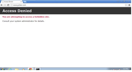
FireSight can also block URL www.poker.com based on category and reputation based filtering (RBF).


FireSight can also be granular by blocking Windows update.


Saturday, September 19, 2015

Configuring Clientless and AnyConnect Remote Access SSL VPNs Using ASDM

We've been using Cisco AnyConnect to VPN back to our corporate network and intranet resources. It gives the same experience as the Cisco's legacy VPN client and also ties back to our Active Directory (AD) profile which allows for single sign-on (SSO). VPN has many flavors and below is one of them, which is the remote access SSL VPN lab that I did on my Cisco ASA 5505 firewall.


Router(config-if)#hostname R1
R1(config)#ip route 0.0.0.0 0.0.0.0 serial0/0/0
R1(config)#interface fastethernet0/0
R1(config-if)#ip address 209.165.200.225 255.255.255.248
R1(config-if)#no shutdown
R1(config-if)#
*Jul  5 03:17:49.787: %LINK-3-UPDOWN: Interface FastEthernet0/0, changed state to up
*Jul  5 03:17:50.787: %LINEPROTO-5-UPDOWN: Line protocol on Interface FastEthernet0/0, changed state to up
R1(config-if)#interface serial0/0/0
R1(config-if)#ip address 10.1.1.1 255.255.255.252
R1(config-if)#no shutdown
R1(config-if)#
*Jul  5 03:18:07.115: %LINK-3-UPDOWN: Interface Serial0/0/0, changed state to down
R1(config-if)#clock rate 64000


Router(config)#hostname R2
R2(config)#interface serial0/0/0
R2(config-if)#ip address 10.1.1.2 255.255.255.252
R2(config-if)#no shutdown
R2(config-if)#
*Jul  5 03:17:55.143: %LINK-3-UPDOWN: Interface Serial0/0/0, changed state to up
*Jul  5 03:17:56.143: %LINEPROTO-5-UPDOWN: Line protocol on Interface Serial0/0/0, changed state to up
R2(config-if)#do ping 10.1.1.1

Type escape sequence to abort.
Sending 5, 100-byte ICMP Echos to 10.1.1.1, timeout is 2 seconds:
!!!!!
Success rate is 100 percent (5/5), round-trip min/avg/max = 28/28/32 ms
R2(config-if)#interface serial0/0/1
R2(config-if)#ip address 10.2.2.2 255.255.255.252
R2(config-if)#no shutdown
R2(config-if)#
*Jul  5 03:18:17.699: %LINK-3-UPDOWN: Interface Serial0/0/1, changed state to down
R2(config-if)#clock rate 64000
R2(config-if)#exit
R2(config)#ip route 209.165.200.224 255.255.255.248 serial0/0/0
R2(config)#ip route 172.16.3.0 255.255.255.0 serial0/0/1


Router(config)#hostname R3
R3(config)#interface fastethernet0/1
R3(config-if)#ip address 172.16.3.1 255.255.255.0
R3(config-if)#no shutdown
R3(config-if)#
*Jul  5 03:22:00.983: %LINK-3-UPDOWN: Interface FastEthernet0/1, changed state to up
*Jul  5 03:22:01.983: %LINEPROTO-5-UPDOWN: Line protocol on Interface FastEthernet0/1, changed state to up
R3(config-if)#interface serial0/0/1
R3(config-if)#ip address 10.2.2.1 255.255.255.252
R3(config-if)#no shutdown
R3(config-if)#
*Jul  5 03:22:24.015: %LINK-3-UPDOWN: Interface Serial0/0/1, changed state to up
*Jul  5 03:22:25.015: %LINEPROTO-5-UPDOWN: Line protocol on Interface Serial0/0/1, changed state to up
R3(config-if)#do ping 10.2.2.2

Type escape sequence to abort.
Sending 5, 100-byte ICMP Echos to 10.2.2.2, timeout is 2 seconds:
!!!!!
Success rate is 100 percent (5/5), round-trip min/avg/max = 28/28/28 ms
R3(config-if)#exit
R3(config)#ip route 0.0.0.0 0.0.0.0 serial0/0/1


R1(config)#ip http server
R1(config)#enable password cisco
R1(config)#line vty 0 4
R1(config-line)#password cisco
R1(config-line)#login
R1(config)#line console 0
R1(config-line)#password cisco
R1(config-line)#login


Switch(config)#hostname S1


Switch(config)#hostname S2


Switch(config)#hostname S3


ciscoasa> enable
Password: <ENTER>
ciscoasa# conf t
ciscoasa(config)#

***************************** NOTICE *****************************

Help to improve the ASA platform by enabling anonymous reporting,
which allows Cisco to securely receive minimal error and health
information from the device. To learn more about this feature,
please visit: http://www.cisco.com/go/smartcall

Would you like to enable anonymous error reporting to help improve
the product? [Y]es, [N]o, [A]sk later: n

In the future, if you would like to enable this feature,
issue the command "call-home reporting anonymous".

Please remember to save your configuration.

ciscoasa(config)# hostname CCNAS-ASA
CCNAS-ASA(config)# domain-name ccnasecurity.com
CCNAS-ASA(config)# enable password cisco
CCNAS-ASA(config)# passwd cisco
CCNAS-ASA(config)# interface ethernet0/0
CCNAS-ASA(config-if)# switchport access vlan 2
CCNAS-ASA(config-if)# no shutdown
CCNAS-ASA(config-if)# interface ethernet0/1
CCNAS-ASA(config-if)# switchport access vlan 1
CCNAS-ASA(config-if)# no shutdown
CCNAS-ASA(config-if)# interface ethernet0/2
CCNAS-ASA(config-if)# switchport access vlan 3
CCNAS-ASA(config-if)# no shutdown
CCNAS-ASA(config-if)# interface vlan1
CCNAS-ASA(config-if)# nameif inside
INFO: Security level for "inside" set to 100 by default.
CCNAS-ASA(config-if)# security-level 100
CCNAS-ASA(config-if)# ip address 192.168.1.1 255.255.255.0
CCNAS-ASA(config-if)# interface vlan2
CCNAS-ASA(config-if)# nameif outside
INFO: Security level for "outside" set to 0 by default.
CCNAS-ASA(config-if)# security-level 0
CCNAS-ASA(config-if)# ip address 209.165.200.226 255.255.255.248
CCNAS-ASA(config-if)# interface vlan3
CCNAS-ASA(config-if)# no forward interface vlan1
CCNAS-ASA(config-if)# nameif dmz
INFO: Security level for "dmz" set to 0 by default.
CCNAS-ASA(config-if)# security-level 70
CCNAS-ASA(config-if)# ip address 192.168.2.1 255.255.255.0
CCNAS-ASA(config-if)# object network inside-net
CCNAS-ASA(config-network-object)# subnet 192.168.1.0 255.255.255.0
CCNAS-ASA(config-network-object)# object network dmz-server
CCNAS-ASA(config-network-object)# host 192.168.2.3
CCNAS-ASA(config-network-object)# access-list OUTSIDE-DMZ extended permit ip any host 192.168.2.3
CCNAS-ASA(config)# object network inside-net
CCNAS-ASA(config-network-object)# nat (inside,outside) dynamic interface
CCNAS-ASA(config-network-object)# object network dmz-server
CCNAS-ASA(config-network-object)# nat (dmz,outside) static 209.165.200.227
CCNAS-ASA(config-network-object)# access-group OUTSIDE-DMZ in interface outside
CCNAS-ASA(config)# route outside 0.0.0.0 0.0.0.0 209.165.200.225
CCNAS-ASA(config)# username admin password cisco123
CCNAS-ASA(config)# aaa authentication telnet console LOCAL
CCNAS-ASA(config)# aaa authentication ssh console LOCAL
CCNAS-ASA(config)# aaa authentication http console LOCAL
CCNAS-ASA(config)# http server enable
CCNAS-ASA(config)# http 192.168.1.0 255.255.255.0 inside
CCNAS-ASA(config)# ssh 192.168.1.0 255.255.255.0 inside
CCNAS-ASA(config)# telnet 192.168.1.0 255.255.255.0 inside
CCNAS-ASA(config)# telnet timeout 10
CCNAS-ASA(config)# ssh timeout 10
CCNAS-ASA(config)# policy-map global_policy
CCNAS-ASA(config-pmap)# class inspection_default
CCNAS-ASA(config-pmap-c)# inspect icmp
CCNAS-ASA(config-pmap-c)# crypto key generate rsa modulus 1024
WARNING: You have a RSA keypair already defined named <Default-RSA-Key>.

Do you really want to replace them? [yes/no]: y
Keypair generation process begin. Please wait...


To configure Clientless SSL VPN Remote Access in ASDM, we go to Wizards > VPN Wizards > Clientless SSL VPN Wizard.


We verify the SSL VPN login (via HTTPS) by opening 209.165.200.226 on a web browser on PC-C.


You'll be redirected to another URL when clicking on Web Mail. For this example, I've used the web server on a Catalyst 3560 switch.


To monitor VPN session in ASDM, we go to Monitoring > VPN > VPN Statistics > Sessions. In CLI, we issue the command show vpn-sessiondb webvpn.


CCNAS-ASA# show vpn-sessiondb webvpn

Session Type: WebVPN

Username     : VPN-User               Index        : 3
Public IP    : 172.16.3.3
Protocol     : Clientless
License      : AnyConnect Premium
Encryption   : Clientless: (1)RC4     Hashing      : Clientless: (1)SHA1
Bytes Tx     : 236858                 Bytes Rx     : 15757
Group Policy : ClientlessVPN-Grp-Pol  Tunnel Group : DefaultWEBVPNGroup
Login Time   : 04:55:06 UTC Sun Jul 5 2015
Duration     : 0h:01m:14s
Inactivity   : 0h:00m:00s
NAC Result   : Unknown
VLAN Mapping : N/A                    VLAN         : none


CCNAS-ASA# write erase
Erase configuration in flash memory? [confirm]
[OK]
CCNAS-ASA# reload
System config has been modified. Save? [Y]es/[N]o:
Proceed with reload? [confirm]
CCNAS-ASA#


***
*** --- START GRACEFUL SHUTDOWN ---
Shutting down isakmp
Shutting down webvpn
Shutting down License Controller
Shutting down File system


***
*** --- SHUTDOWN NOW ---
Process shutdown finished


<OUTPUT TRUNCATED>

ciscoasa> enable
Password:
ciscoasa# conf t
ciscoasa(config)#

***************************** NOTICE *****************************

Help to improve the ASA platform by enabling anonymous reporting,
which allows Cisco to securely receive minimal error and health
information from the device. To learn more about this feature,
please visit: http://www.cisco.com/go/smartcall

Would you like to enable anonymous error reporting to help improve
the product? [Y]es, [N]o, [A]sk later: n

In the future, if you would like to enable this feature,
issue the command "call-home reporting anonymous".

Please remember to save your configuration.

ciscoasa(config)# hostname CCNAS-ASA
CCNAS-ASA(config)# domain-name ccnasecurity.com
CCNAS-ASA(config)# enable password cisco
CCNAS-ASA(config)# passwd cisco
CCNAS-ASA(config)# interface ethernet0/0
CCNAS-ASA(config-if)# switchport access vlan 2
CCNAS-ASA(config-if)# no shutdown
CCNAS-ASA(config-if)# interface ethernet0/1
CCNAS-ASA(config-if)# switchport access vlan 1
CCNAS-ASA(config-if)# no shutdown
CCNAS-ASA(config-if)# interface ethernet0/2
CCNAS-ASA(config-if)# switchport access vlan 3
CCNAS-ASA(config-if)# no shutdown
CCNAS-ASA(config-if)# interface vlan 1
CCNAS-ASA(config-if)# nameif inside
INFO: Security level for "inside" set to 100 by default.
CCNAS-ASA(config-if)# security-level 100
CCNAS-ASA(config-if)# ip address 192.168.1.1 255.255.255.0
CCNAS-ASA(config-if)# interface vlan 2
CCNAS-ASA(config-if)# nameif outside
INFO: Security level for "outside" set to 0 by default.
CCNAS-ASA(config-if)# security-level 0
CCNAS-ASA(config-if)# ip address 209.165.200.226 255.255.255.248
CCNAS-ASA(config-if)# interface vlan 3
CCNAS-ASA(config-if)# no forward interface vlan 1
CCNAS-ASA(config-if)# nameif dmz
INFO: Security level for "dmz" set to 0 by default.
CCNAS-ASA(config-if)# security-level 70
CCNAS-ASA(config-if)# ip address 192.168.2.1 255.255.255.0
CCNAS-ASA(config-if)# object network inside-net
CCNAS-ASA(config-network-object)# subnet 192.168.1.0 255.255.255.0
CCNAS-ASA(config-network-object)# nat (inside,outside) dynamic interface
CCNAS-ASA(config-network-object)# exit
CCNAS-ASA(config)# object network dmz-server
CCNAS-ASA(config-network-object)# host 192.168.2.3
CCNAS-ASA(config-network-object)# nat (dmz,outside) static 209.165.200.227
CCNAS-ASA(config-network-object)# exit
CCNAS-ASA(config)# access-list OUTSIDE-DMZ extended permit ip any host 192.168.2.3
CCNAS-ASA(config)# access-group OUTSIDE-DMZ in interface outside
CCNAS-ASA(config)# route outside 0 0 209.165.200.225
CCNAS-ASA(config)# username admin password cisco123 privilege 15
CCNAS-ASA(config)# aaa authentication telnet console LOCAL
CCNAS-ASA(config)# aaa authentication ssh console LOCAL
CCNAS-ASA(config)# aaa authentication http console LOCAL
CCNAS-ASA(config)# http server enable
CCNAS-ASA(config)# http 192.168.1.0 255.255.255.0 inside
CCNAS-ASA(config)# ssh 192.168.1.0 255.255.255.0 inside
CCNAS-ASA(config)# telnet 192.168.1.0 255.255.255.0 inside
CCNAS-ASA(config)# telnet timeout 10
CCNAS-ASA(config)# ssh timeout 10
CCNAS-ASA(config)# policy-map global_policy
CCNAS-ASA(config-pmap)# class inspection_default
CCNAS-ASA(config-pmap-c)# inspect icmp
CCNAS-ASA(config-pmap-c)# exit
CCNAS-ASA(config-pmap)# crypto key generate rsa modulus 1024
WARNING: You have a RSA keypair already defined named <Default-RSA-Key>.

Do you really want to replace them? [yes/no]: y
Keypair generation process begin. Please wait...
CCNAS-ASA(config)#


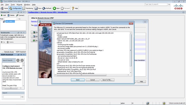
To configure AnyConnect SSL VPN Remote Access using ASDM, we to go Wizards > VPN Wizards > AnyConnect VPN.


We login to https://209.165.200.226 from PC-C and it will automatically go through the process of downloading the AnyConnect VPN client.


CCNAS-ASA# show vpn-sessiondb anyconnect

Session Type: AnyConnect

Username     : VPN-User               Index        : 2
Assigned IP  : 192.168.1.33           Public IP    : 172.16.3.3
Protocol     : Clientless SSL-Tunnel DTLS-Tunnel
License      : AnyConnect Premium
Encryption   : Clientless: (1)RC4  SSL-Tunnel: (1)RC4  DTLS-Tunnel: (1)AES128
Hashing      : Clientless: (1)SHA1  SSL-Tunnel: (1)SHA1  DTLS-Tunnel: (1)SHA1
Bytes Tx     : 118089                 Bytes Rx     : 112949
Group Policy : GroupPolicy_AnyC-SSL-VPN-Con-Prof
Tunnel Group : AnyC-SSL-VPN-Con-Prof
Login Time   : 10:35:42 UTC Sun Jul 5 2015
Duration     : 0h:06m:42s
Inactivity   : 0h:00m:00s
NAC Result   : Unknown
VLAN Mapping : N/A                    VLAN         : none